MANE 3351
Lecture 29, November 29
Classroom Management
Agenda
- Lecture
- Will be available in Lab
Resources
Part Two Calendar
| Lecture | Date | Content |
|---|---|---|
| 19 | October 25 | Vectors |
| 20 | October 27 | Vectors (part 2) |
| 21 | November 1 | Midterm Exam |
| 22 | November 3 | Programming |
| 23 | November 8 | Matrix Multiplication and Determinants |
| 24 | November 10 | Determinants and Matrix Inversion |
| 25 | November 15 | Matrix Inversion, Gauss-Jordan Elimination |
| 26 | November 17 | Homework 6 |
| 27 | November 22 | Gaussian Elimination with Partial Pivoting |
| 28 | November 24 | Pandas, Octave, Gnu Plot |
| 29 | November 29 | Circuits, GPIO, Arduinos |
Assignments
Lecture 29 Overview
- Electronics Review
- Raspberry PI - GPIO
- Arduinos
Circuit
An electronic circuit is a complete course of conductors through which current can travel. Circuits provide a path for current to flow. To be a circuit, this path must start and end at the same point. In other words, a circuit must form a loop. An electronic circuit and an electrical circuit has the same the same definition, but electronic circuits tend to be low voltage circuits.
Source:What is an Electronic Circuit
Elements of Circuit
- Voltage source: A voltage source causes current to flow like a battery
- Load: The load consumes power; it represents the actual work done by the circuit. Without the load, there's not much point in having a circuit
- Conduct path: The conductive path provides a route through which current flows. This route begins at the voltage source, travels through the load, and then returns to the voltage source. This path must form a loop from the negative side of the voltage source to the positive side of the voltage source.
Source:What is an Electronic Circuit
Points about Circuits
When a circuit is complete and forms a loop that allows current flow, the circuit is called a closed circuit. If any part of the circuit is disconnect or disrupted so that a loop is not formed, current cannot flow. In that case, the circuit is called an open circuit.
Short circuit refers to a circuit that does not have a load. For example, if the lamp is connected to the circuit but a direct connection is present between the battery’s negative terminal and its positive terminal, too.
Warning! Current in a short circuit can flow at dangerously high levels. Short circuits can damage electronic components, cause a battery to explode, or maybe start a fire.
Current flows everywhere it can. If your circuit has two pathways through which current can flow, the current doesn’t choose one over the other; it chooses both. However, not all paths are equal, so current doesn’t flow equally through all paths.
Source:What is an Electronic Circuit
Voltage, Current, and Resistance
An electric circuit is formed when a conductive path is created to allow electric charge to continuously move. This continuous movement of electric charge through the conductors of a circuit is called a current, and it is often referred to in terms of “flow,” just like the flow of a liquid through a hollow pipe.
The force motivating charge carriers to “flow” in a circuit is called voltage. Voltage is a specific measure of potential energy that is always relative between two points.
When we speak of a certain amount of voltage being present in a circuit, we are referring to the measurement of how much potential energy exists to move charge carriers from one particular point in that circuit to another particular point. Without reference to two particular points, the term “voltage” has no meaning.
Current tends to move through the conductors with some degree of friction, or opposition to motion. This opposition to motion is more properly called resistance. The amount of current in a circuit depends on the amount of voltage and the amount of resistance in the circuit to oppose current flow.
Just like voltage, resistance is a quantity relative between two points. For this reason, the quantities of voltage and resistance are often stated as being “between” or “across” two points in a circuit.
Source: Ohms Law - How Voltage, Current, and Resistance Relate
Units of Measurement: Volt, Amp, and Ohm
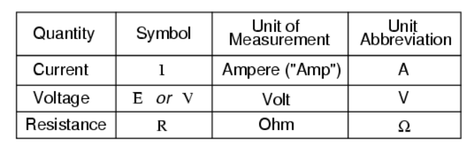
Source: Ohms Law - How Voltage, Current, and Resistance Relate
The Ohm's Law Equation
Source: Ohms Law - How Voltage, Current, and Resistance Relate
4 Band Resistor Color Code
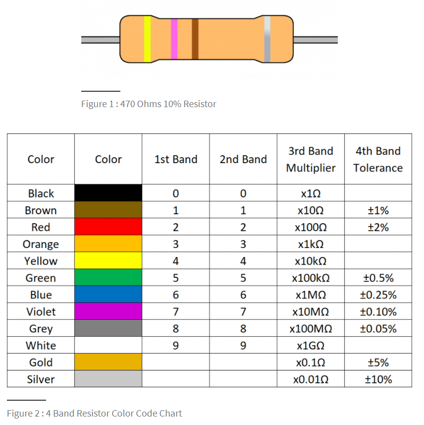
Source: Resistor Color Codes
Resistors used in Our Labs
We will use two resistors in our circuits. These resistors will have three color bands (we are ignoring the fourth band, tolerance)
- Red, Red, Brown (third band, brown, gives multiplier) $$ 22\times 10\Omega=220\Omega\nonumber $$
- Brown, Black, Orange $$ 10\times1k\Omega=10k\Omega\nonumber $$
Breadboard Layout - Horizontal Rows
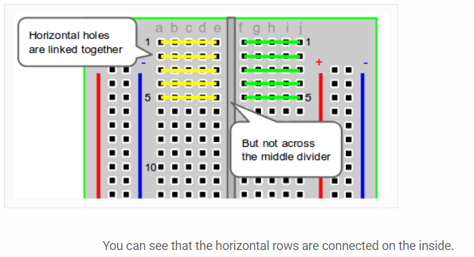
Source: How to use a breadboard and build a led circuit
Breadboard Layout - Vertical Columns
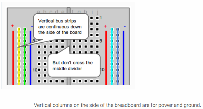
Source: How to use a breadboard and build a led circuit
General Purpose Input/Output
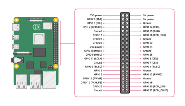
Source: Raspberry Pi Documentation
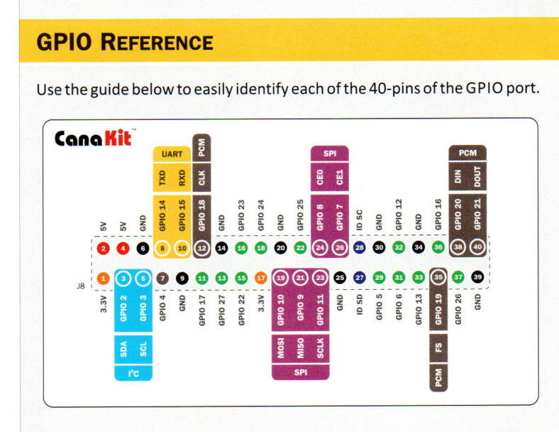
GPIO
- Voltages - Two 5V pins and two 3v3 pins are present on the board as well as ground pins (0v)
- Outputs - A GPIO pin designated as an output pin can be set to high (3V3) or low (0v)
- Inputs- A GPIO designated as an input pin can be read as high (3V3) or low (0V). This is made easier with the use of internall pull-up or pull-down resistors. GPIO2 and GPIO3 have fixed pull-up resistors, but for other pins this can be configured in software.
- More - Additional functionality is available on GPIO pins
GPIO in Python
- Documentation of using GPIO in Python is available at https://www.raspberrypi.org/documentation/usage/gpio/python/README.md
Schematic for Lab 9
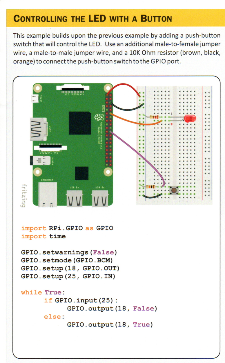
Light-emitting Diode
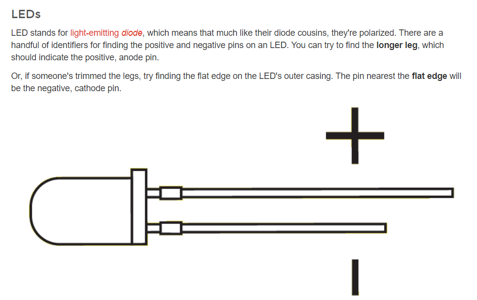
Source: https://learn.sparkfun.com/tutorials/polarity/diode-and-led-polarity
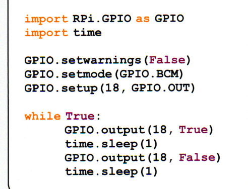
Example 1, Blinking an LED
Source: CanaKit Raspberry Pi 4 Quick-start Guide
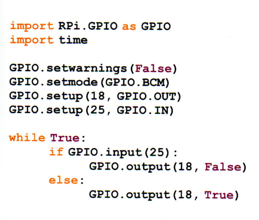
Example 2, Controlling an LED
Source: CanaKit Raspberry Pi 4 Quick-start Guide
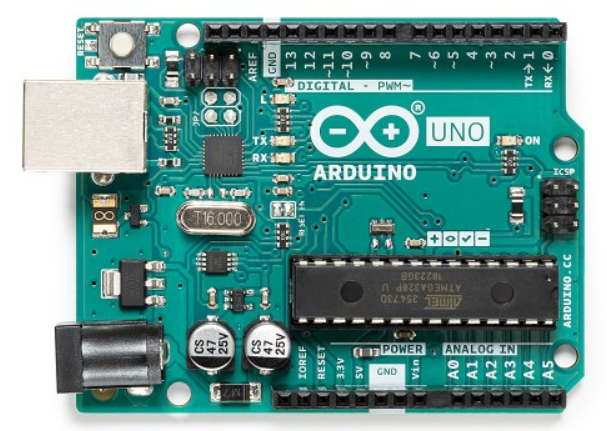
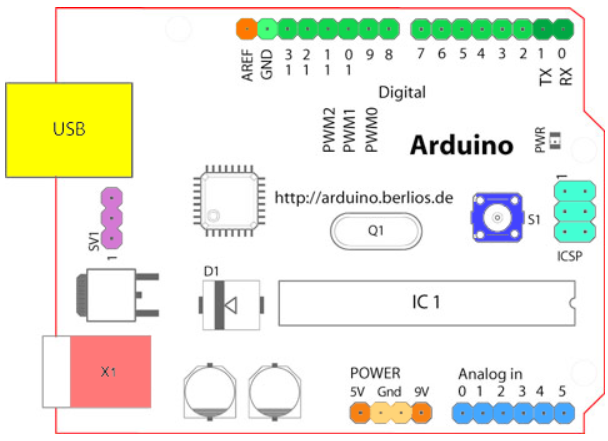
Arduino Uno
Source: Arduino Uno Website
Source: Arduino Website
Input/Output
- Voltages - 5V pin and 9V pin are present on the board as well as ground pins (0v)
- Digital Pins - multiple digital pins are provided on an Arduino board that can be used for general purpose input and output via the pinMode(), digitalRead(), and digitalWrite() commands
- Analog Pins- the analog input pins suport 10-bit analog-to-digital conversion using the analogRead() function
- Other Pins - A reference voltage and reset functionality are also available
Arduino Mega
- There are multiple versions of Arduino boards.
- The Arduino Mega is often combined with a RAMPS shield to construct homemade Reprap 3D-printers
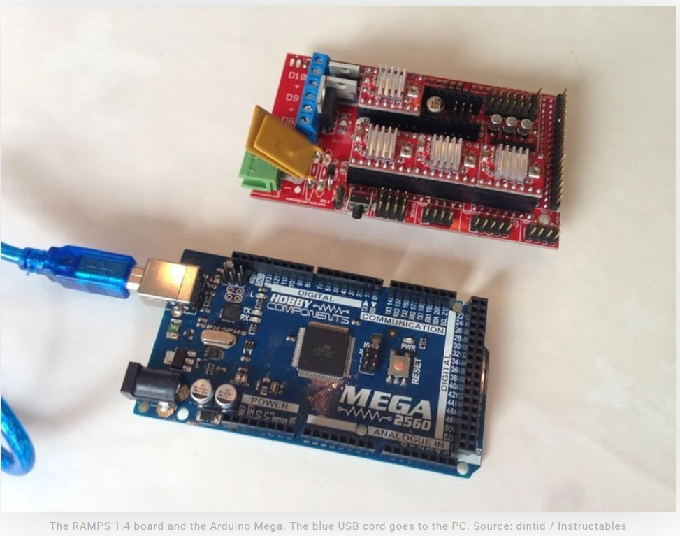
Source: all3dp
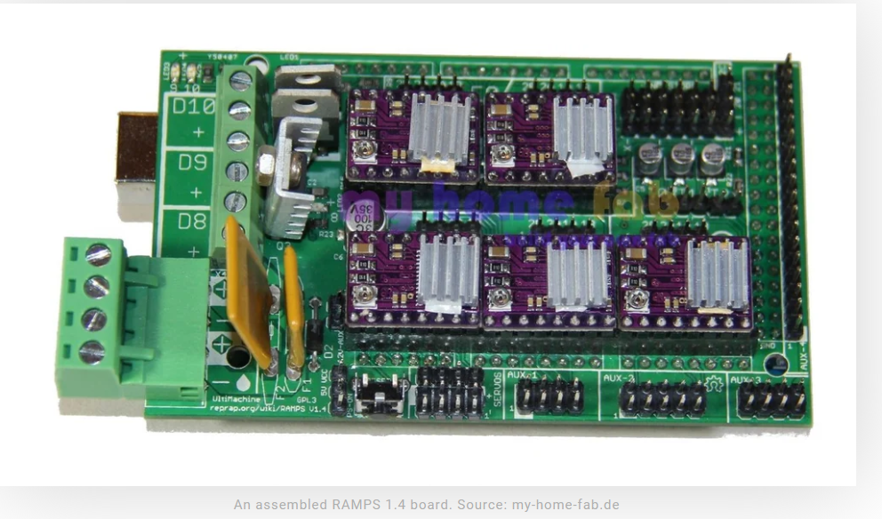
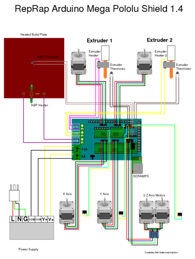
RAMPS Shield
- Circuit board that plugs into Arduino Mega for build 3D printers
- Typically includes drivers for stepper motors shown below
- Schematic for 3D printer is also provided below
- Both images taken from All3DP website
Programming Arduino
- Written in the Arduino Integrated Development Environment
- Arduino programming language is based on a very simple hardware programming language called processing, which is similar to the C language
- Programs for Arduinos are called sketches
- Sketches must be uploaded to Arduino (via USB cable)
- Arduino IDE installed on Raspberry Pi
Source: Programming Arduinos
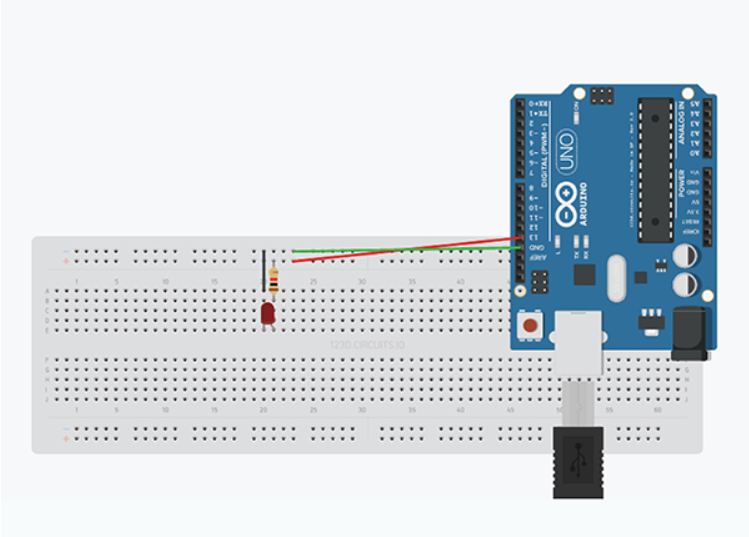
Example 1: Blinking an LED
- First example is to an LED (same as with the Raspberry Pi)
Example 1: Sketch
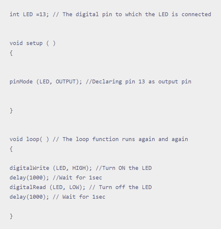
- Note: there is an error in the sketch. Change digitalRead to digitalWrite
Warning
- Arduinos store the last program in EEPROM and will start running that program as soon as the power is provided
- Cautious Approach:
- Do not connect circuit board to Arduino until after the Sketch is loaded
- Afterwards, connect hardware
Example 2: LED with a Switch
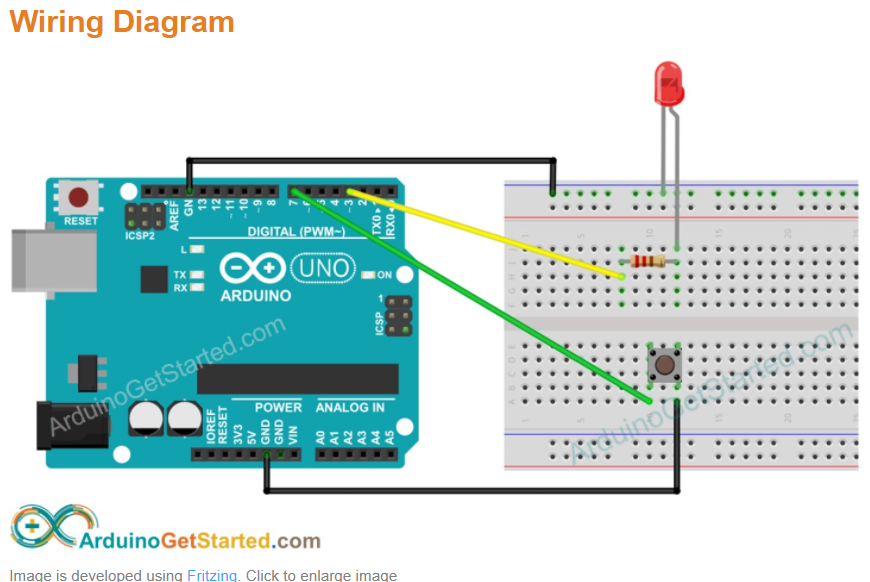
Source: ArduinoGetStarted
Example 2: Sketch
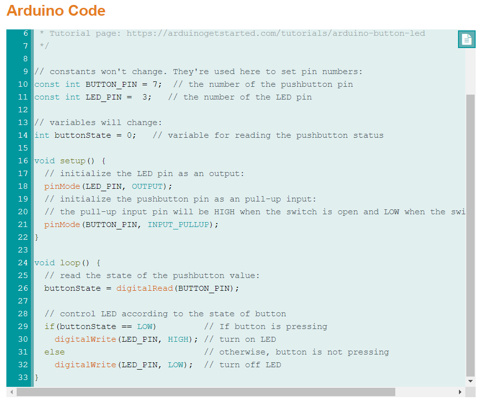
Source: ArduinoGetStarted